Wye Valley Precision Engineering manufactures the rubber component for the AB05 Miniature Bayonet Coupling Connectors.
Shell: Aluminum Alloy
Insulator: Polychloroprene
Grommet: Polychoroprene
Contacts: Brass
Accessory: Aluminum Alloy
Shell: Conductive, Olive Drab over cadmium plate
(Alternatives available on request)
Contacts: Gold over nickel
Accessory: Conductive, Olive Drab over cadmium plate
(Alternatives available on request)
Environmental Ratings:
Shock: 100g
Vibration: 10 to 5000 Hz long endurance, 30- hour at 10g
Acceleration: 50g
Humidity severity: 44 millibars
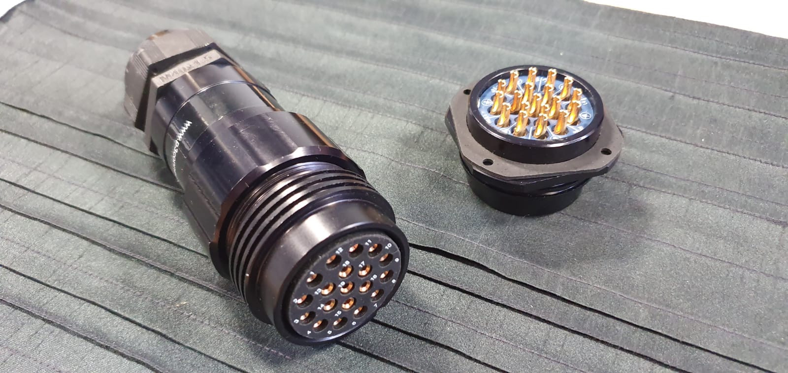
1. Free Shell – Holds the insert.
2. Grounding Finger – Ensures RFI grounding when connectors are mated.
3. Coupling Nut – Provides cam force
4. Wave Washer – Provides the coupling force when mating and un-mating
connectors
5. Skid Washer – Retains the wave Washer.
6. Circlip – Retains the Coupling Nut to the Free Shell.
7. Insert – Retains & Insulates the Contacts.
8. Contacts – Crimped or soldered to the conductors.

1. Fixed Shell – Holds the Insert.
2. Seating Face Gasket – Seals the connectors when mated.
3. Insert – Retains & Insulates the Contacts.
4. Contacts – Crimped or soldered to the conductors.
5. Bayonet Pins – Provides the method of mating the Connectors together.
